solid state relay (SSR) is an electronic switch, which, unlike an electromechanical relay, contains no moving parts. The types of SSR are photo-coupled SSR, transformer-coupled SSR, and hybrid SSR. A photo-coupled SSR is controlled by a low voltage signal which is isolated optically from the load. The control signal in a photo-coupled SSR typically energizes an LED which activates a photo-sensitive diode. The diode turns on a back-to-back thyristor, silicon controlled rectifier, or MOSFET transistor to switch the load.
source : http://idobartana.com/hakb/SSR/circuit.html
The circuit for a solid-state relay is quite simple. Here is the schematic:
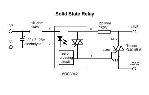
The center of the circuit is the MOC3042 or MOC3041 optoisolator. The difference between these parts is the current required to trigger the internal LED. When a current source is introduced between V+ and V-, the 22uF capacitor is charged. The 1K resistor limits the current from the cap into the optoisolator and causes the LED to illuminate inside the chip. Line voltage flows through the 22 ohm resistor and into the zero-crossing circuit in the optoisolator. When the zero-crossing circuit detects a zero crossing voltage and the LED is illuminated, the gate on the triac in the optoisolator is triggered with the same phase as the phase of the line voltage. This line phase current is then used as the gate trigger to the alternistor. This causes the line current to flow through the alternistor and power the load. Remember, this circuit only works if line current is fed into pin 6 of the optoisolator. If you hook the circuit up wrong, the zero-crossing circuit will not detect the voltage zero crossing and will not trigger the alternistor. The Lamp Module and the Wall Switch circuits are very similar. The X-10 chip has an output pin driving a transistor to switch -15V. This signal in conjunction with a couple of diodes and a couple of resistors is used to trigger the triac. If we remove the triac, the two resistors and the two diodes, we can insert the above solid state relay circuit and the output of that SSR circuit can power small appliances and fluorescent lights. The SSR circuit V- could be connected to the transistor, since it has a potential of -15V and V+ could be connected to the logical ground of the Lamp or Wall Switch circuit.